Power dividers and combiners are used in microwave frequencies because of the different behavior of circuits. In microwave frequencies, the modeling of the circuits are different from the expected lumped model. Therefore, power dividers in microwave frequencies are not just resistive power dividers as in the low frequency or DC model. The important issues while using power dividers, are the specifications or properties of the dividers. In microwave frequency applications, for example power can be reflected from the output ports. Then to avoid the reflected power expected power divider should satisfy the maximum power transfer theory, which says the impedance of the load should be the complex conjugate of the impedance seen from the load end when load is not connected. This is called "matching" of the ports. This leads to transferring maximum power to the load and because of no reflection, avoid to burn out the power supply. Also, again for maximally transfer the power to the output ports, the network should not dissipate power and this property is called "losslessness".
There are three types of dividers we analyze:
1-) WILKINSON
2-) T-JUNCTION
3-) SPLIT-TEE
Wilkinson Power Divider
Wilkinson power divider is a solution of the loss less T-junction problems, which are not matched and non-isolated output ports. The resistive T-junction divider can be a solution for the matching problem but the isolation part cannot be solved and also this solution leads a power loss because of the resistive structure of the resistive T-junction divider. Wilkinson power divider is a lossy three port network and it has a property of being lossless when the output ports are matched. In addition, the isolation between output ports are can be achieved in Wilkinson power divider. Dissipated power in the Wilkinson power divider is from the reflected power. There are two general type of the Wilkinson power dividers; first one is the equal power divider and the second one is unequal power divider.
Wilkinson Equal Power Dividers
The equal power division concept is dividing input power to equal or more than two ways equally. The mostly used one is the three port network equal two way divider. It is also called 3 dB power divider.
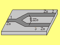
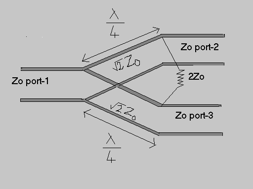
In this type of dividers, there are four different sections. 1-) Input port 2-) Quarter-wave transformers 3-) Isolation resistors 4-) Output ports Input and output ports are identical and the value of the impedances of them are Zo. Quarter-wave transformer parts are called as quarter-wave transformer because of the length of these parts. The length of these parts are equal to the one fourth of the wavelength of the electromagnetic wave, which is propagating in this three port network. This length is also related to the operation frequency. Wavelength * Frequency = Phase velocity (Usually the speed of light) Why the quarter-wave transformers are used in the circuit? The reason for this leads us to understand the matching conditions for this network. Matching of the output ports is necessary for the better power transfer from input to output, because if the output ports are matched, the reflected power from the network when we input some amount of power is zero. This means, there is no reflection from the outputs and all of the power is transmitted to the output ports. Consider the case of inputing power at port 1 and terminate the ports 2 and 3 with the reference loads. Then the reflected power for inputing power at port-1 is zero ( S11 = 0 ). All the power is transferred at that frequency. The quarter-wave transformer part leads to the matched ports. Isolation resistor is to isolate the output ports. If there is a coupling effect between output ports or in other words, the power comes from one output port has an effect on other output port, the perfect division of the power cannot be possible. This isolation resistor avoids the coupling effects of the output ports. Output ports are the ports that divided power comes to. These ports have the same impedance value with the input port's impedance. To analyze the Wilkinson power divider, even-odd mode analysis method is used. In even-odd mode analysis the aim is finding the S-parameters of the divider. S-parameters give all voltage and power information about the network we consider. To find S-parameters, from the definition of them, we should input power at a port and measure the contributions of that power to the other ports. In even-odd mode analysis, the superposition of the two modes is inputing power at port-2 and finding the effects at all ports. First of all our circuit becomes symmetric, made symmetric with respect to the axis at the middle. This symmetricity makes the analyze easy. | ||
| Please contact with questions or comments. Prof. M. Irsadi Aksun, Electrical and Electronics Engineering Dept. Bilkent University, Ankara, Turkey Email: irsadi@ee.bilkent.edu.tr |


No comments:
Post a Comment